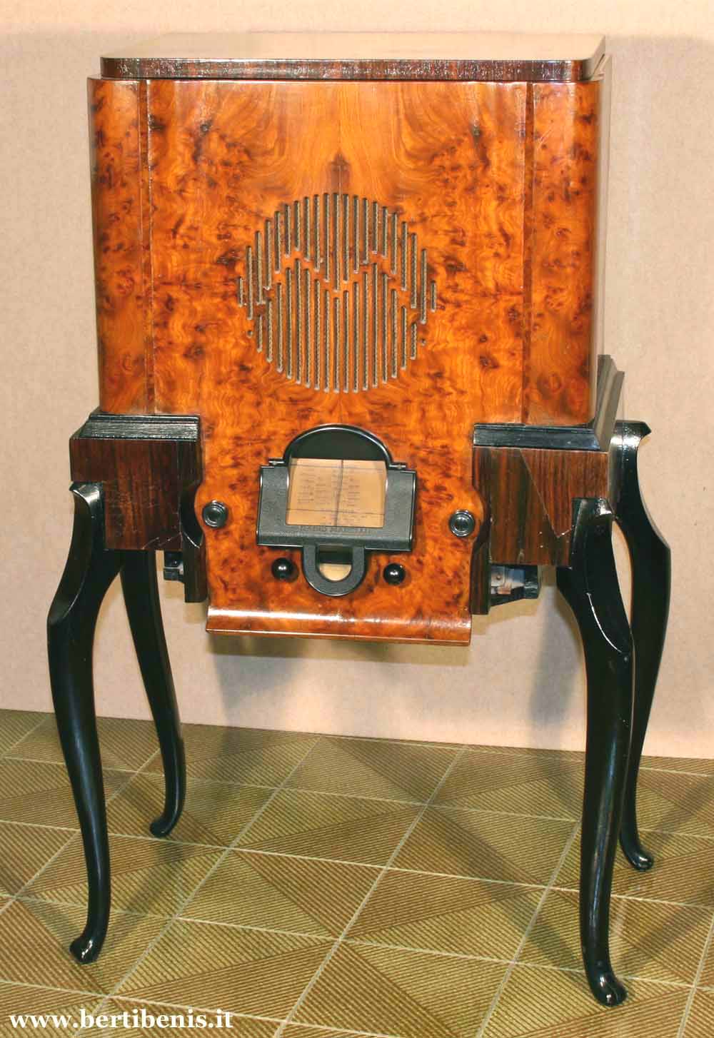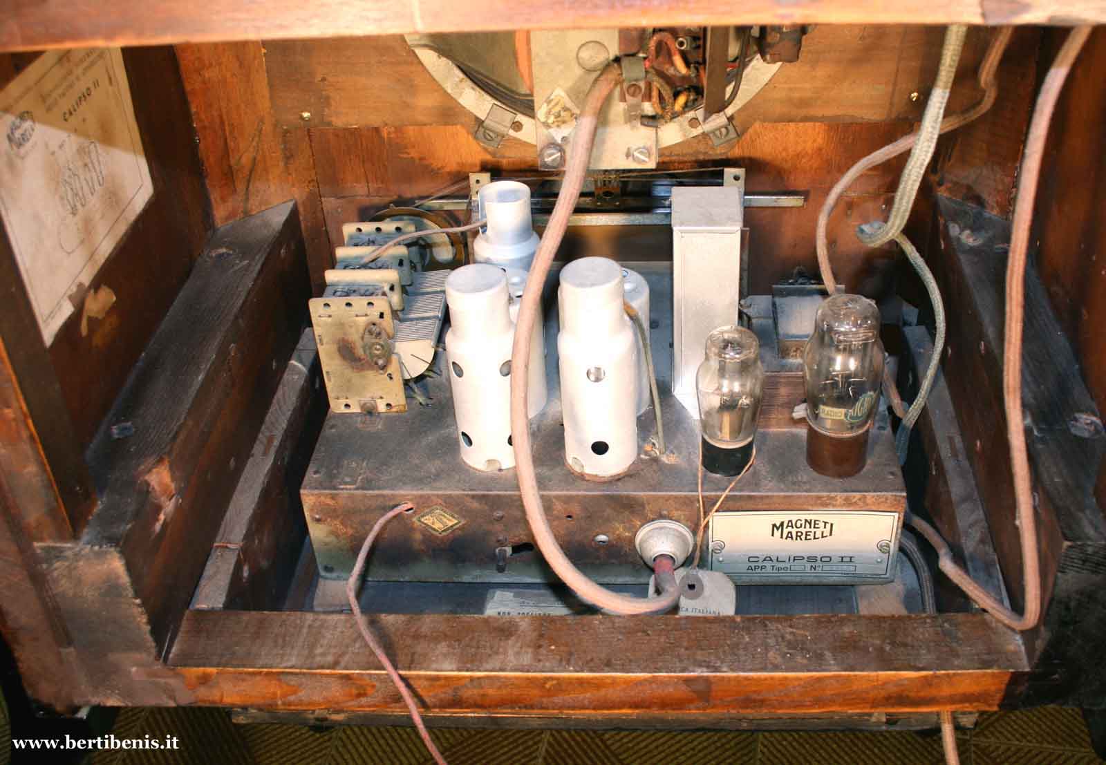
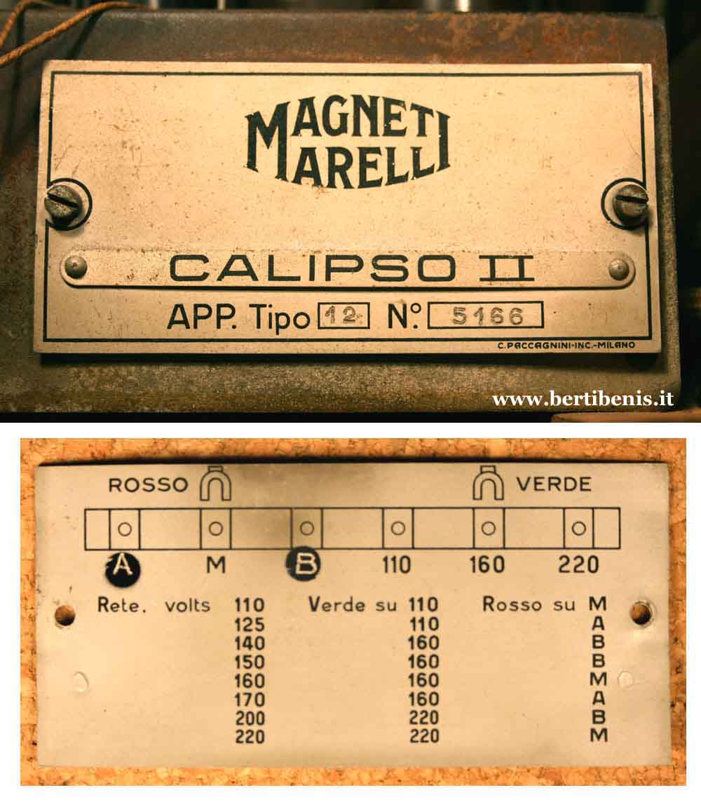
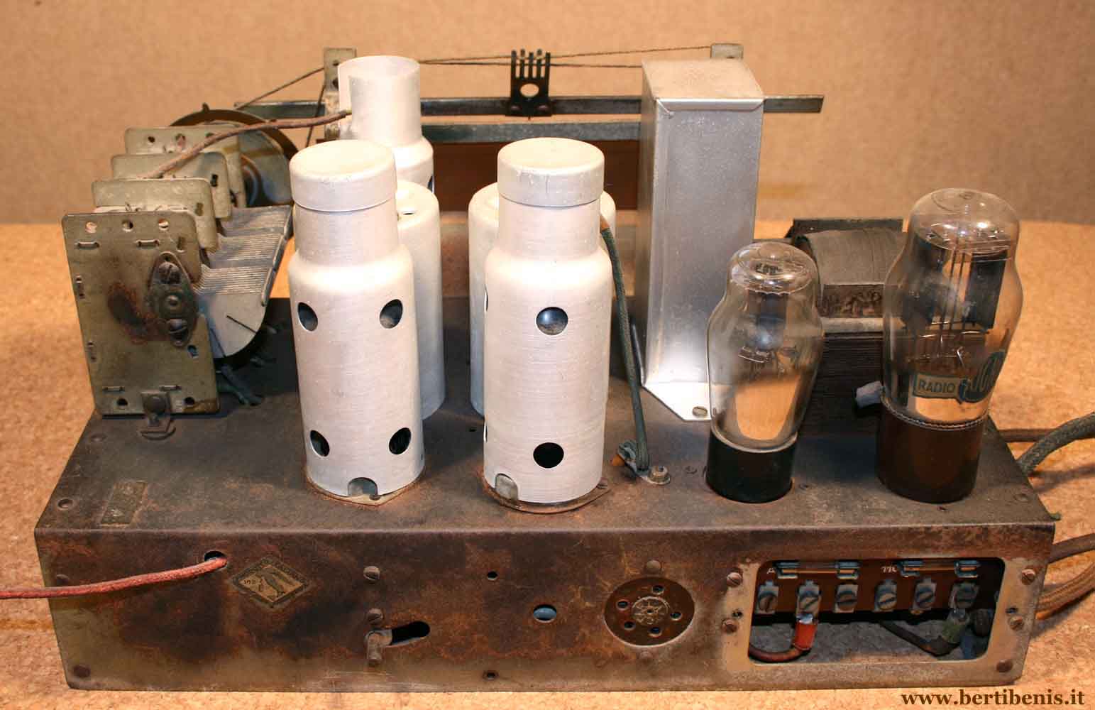
Radiomarelli CALIPSO II
( 12 type set ) |
Calipso
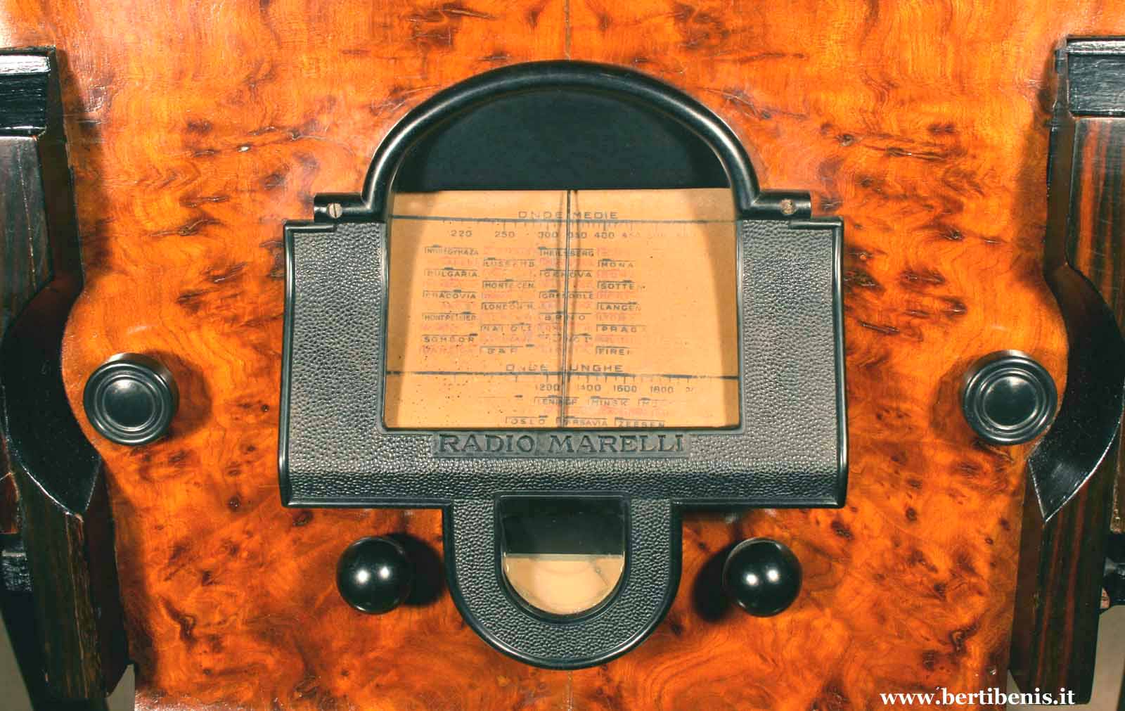
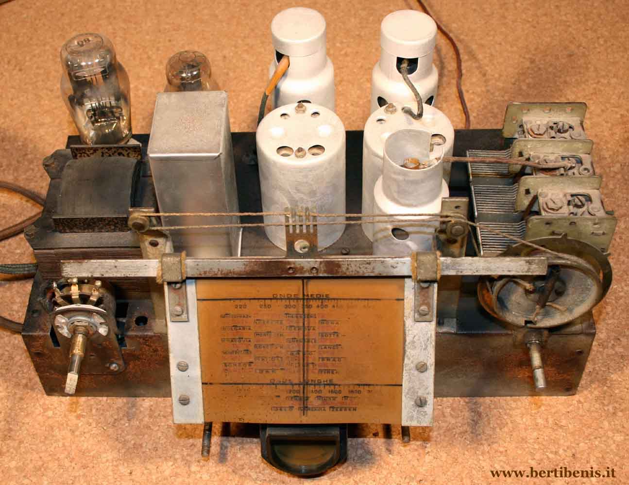
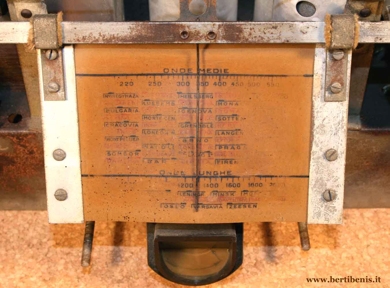
II differs from the first version for the tuning dial and it can
receive two bands, medium and long waves. Electric
diagram and chassis are not similar to the one of Calipso (first
version). Calipso
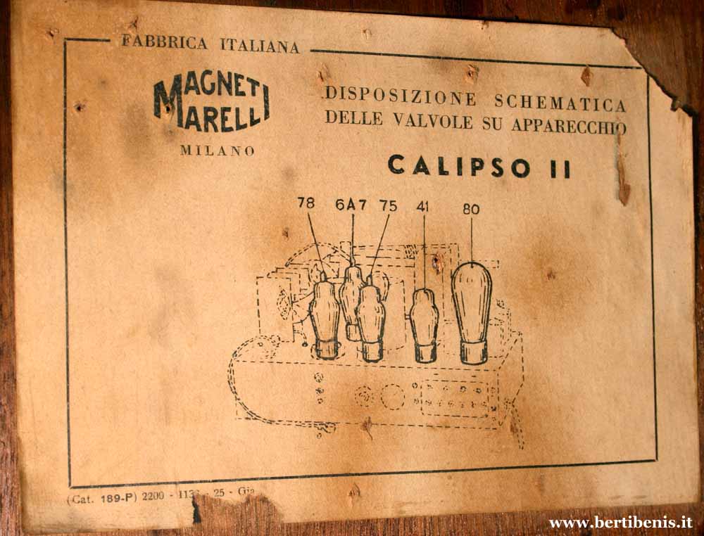
II is a superheterodyne set also but, compared to the first version,
the diagram is more evolved. In this radio was used an indirect 6,3 V
heater new tube series and the frequency converter is a multi-grid
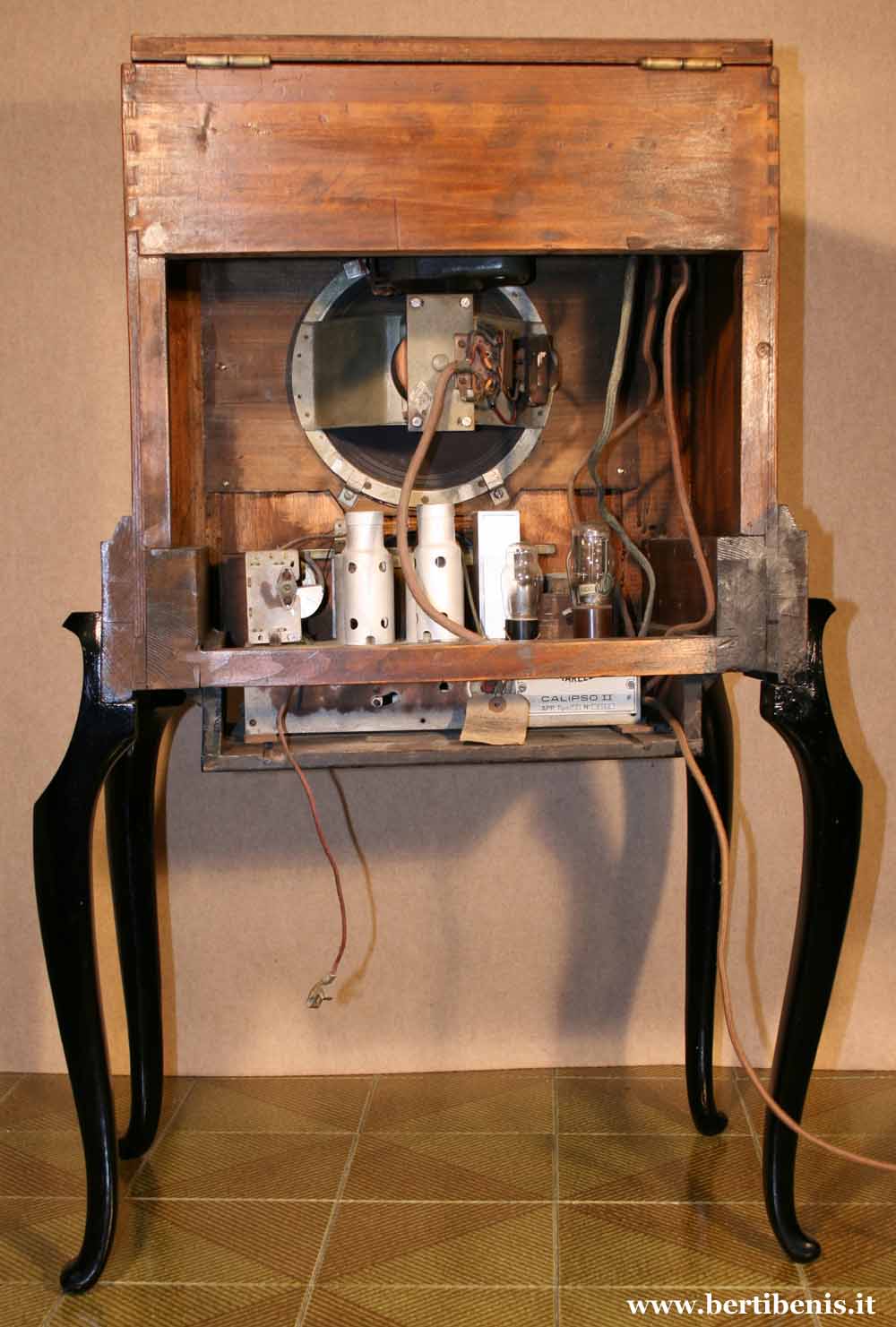
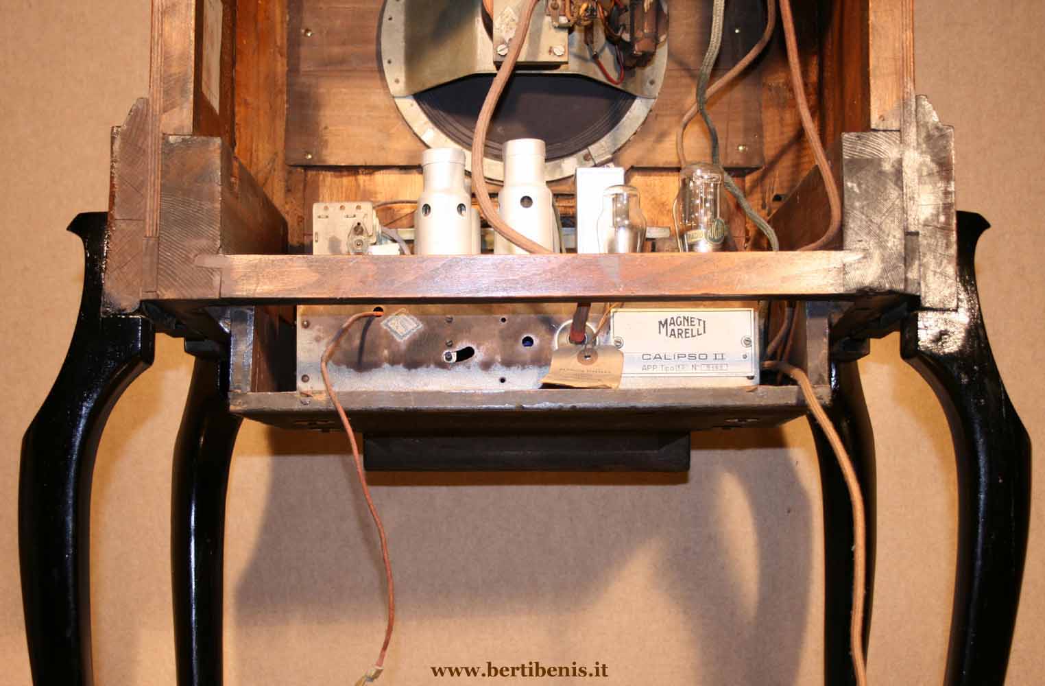
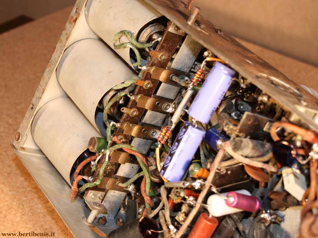
tube, 6A7. Diagram
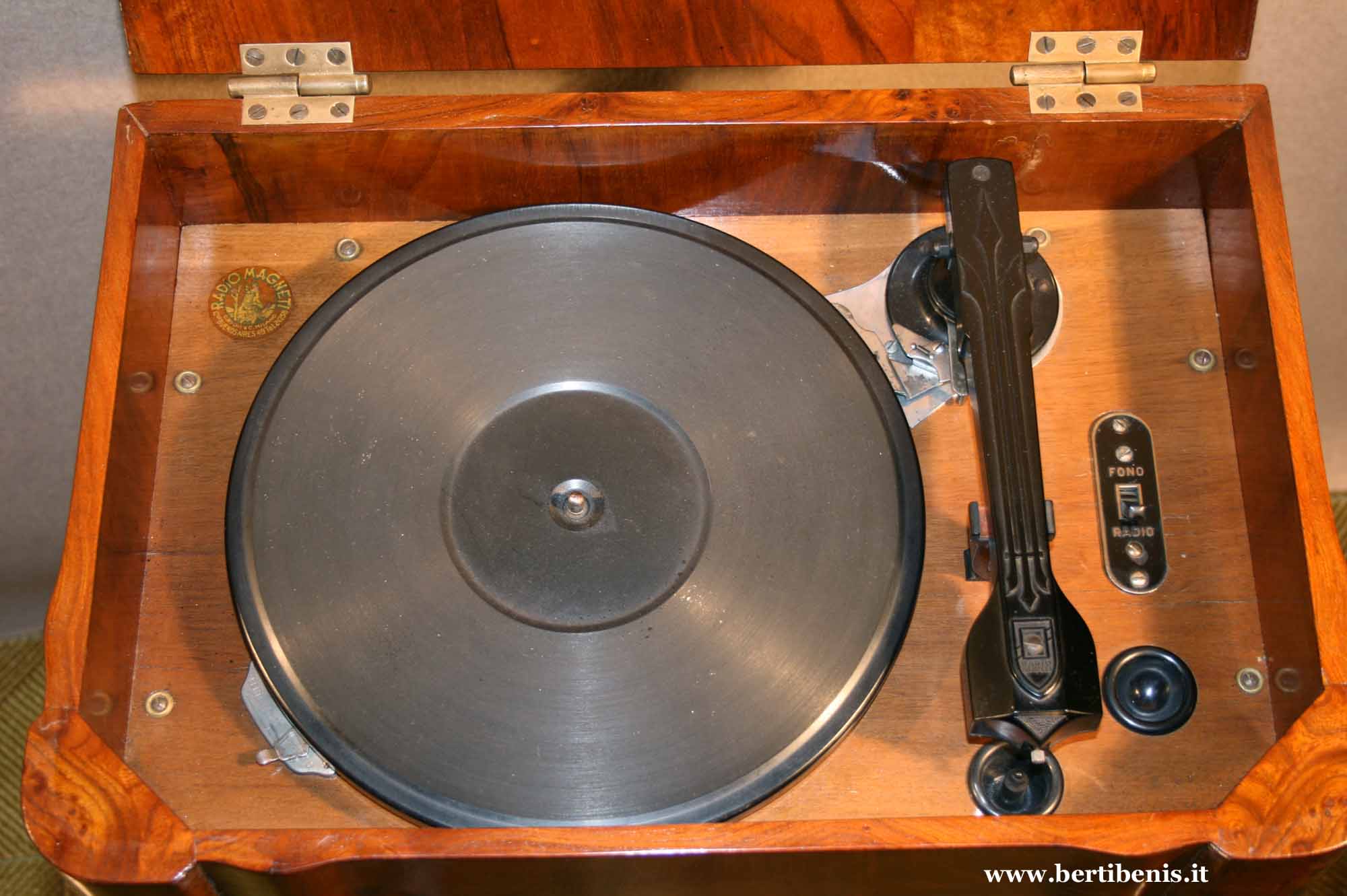
and chassis of this radio are same to the ones of Damayante model. The
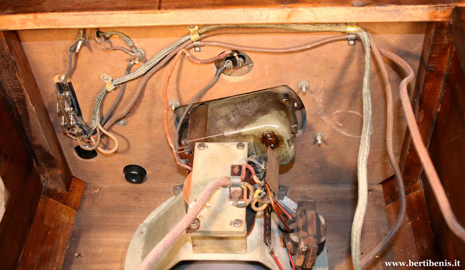
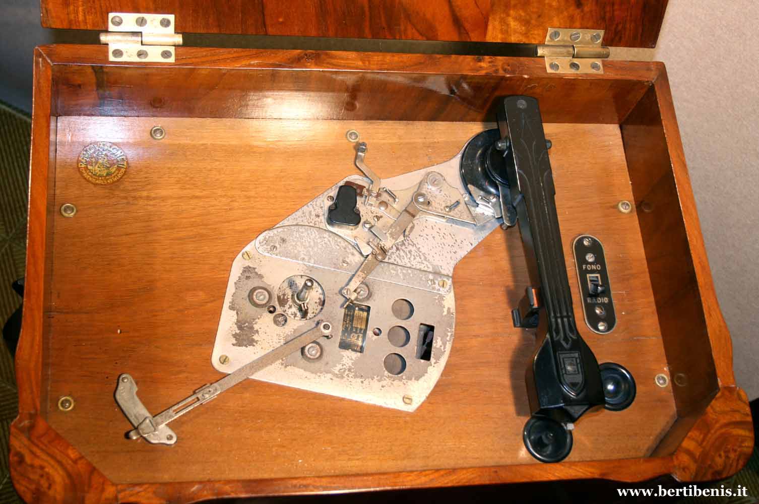
turntable, which works only 78
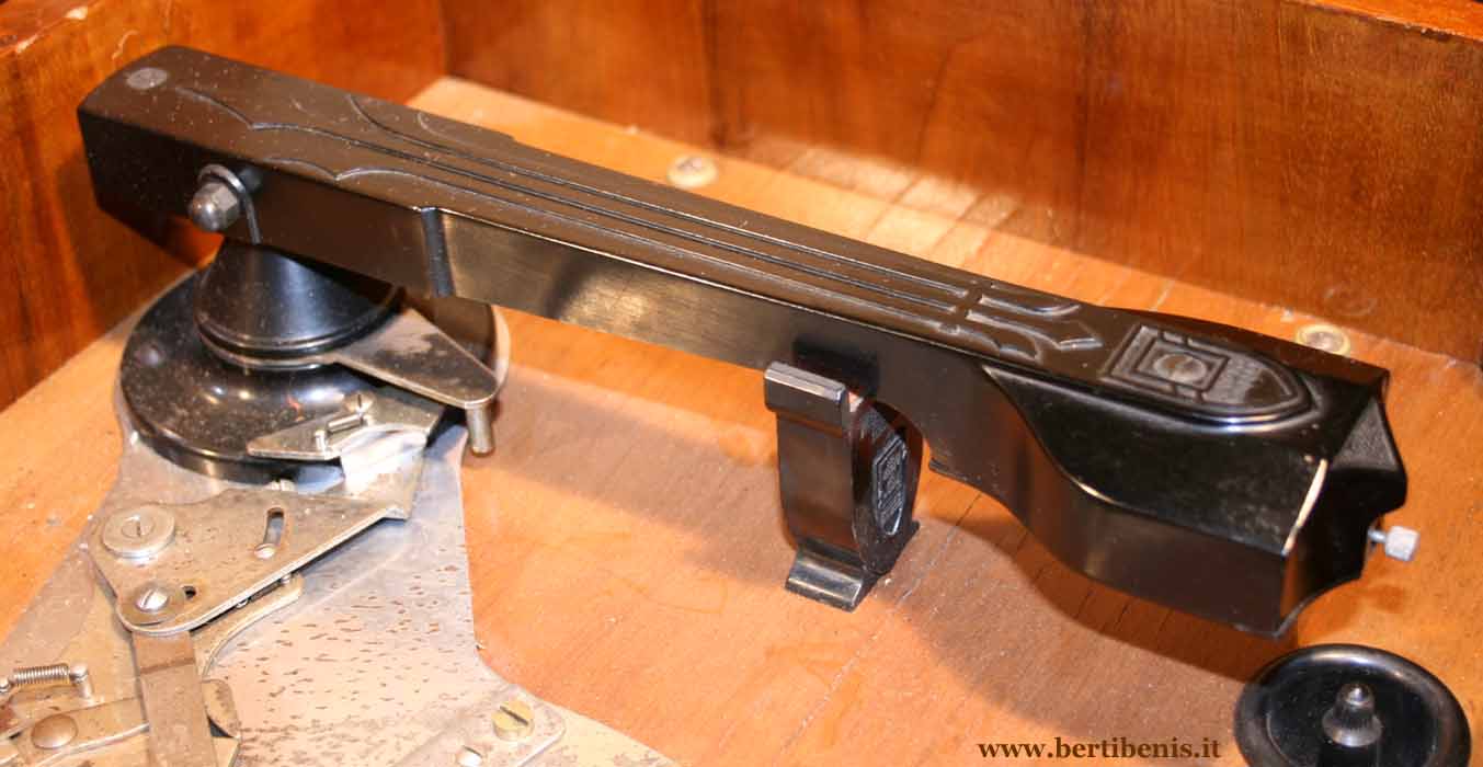
laps, has the pick-up with the interchangeable pin system, like a gramophone. The electric
motor is a Paillard mod. 4000 (Swiss made) while arm and platen were
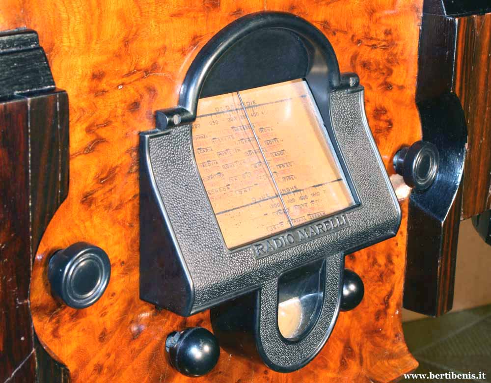
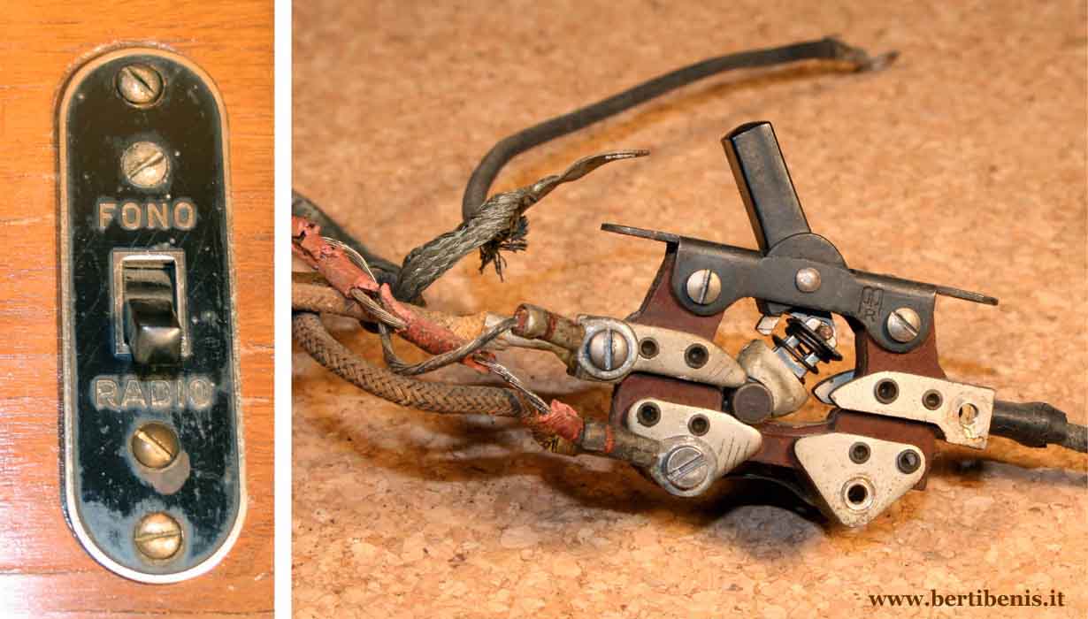
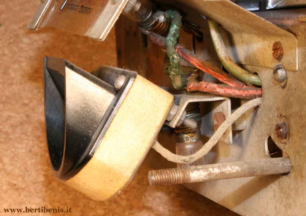
manufactured by Radiomarelli. The upper left knob operates the power switch / volume control while the
right one is for the tuning. The lower left knob (spherical in shape)
has two axial positions and is
used to remove the sound without switching off the radio. The
right one spherical knob has two axial positions also and operates
the switch band, by pulling toward yourself you select the long
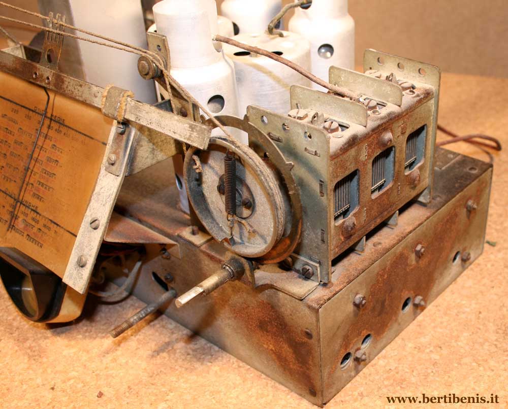
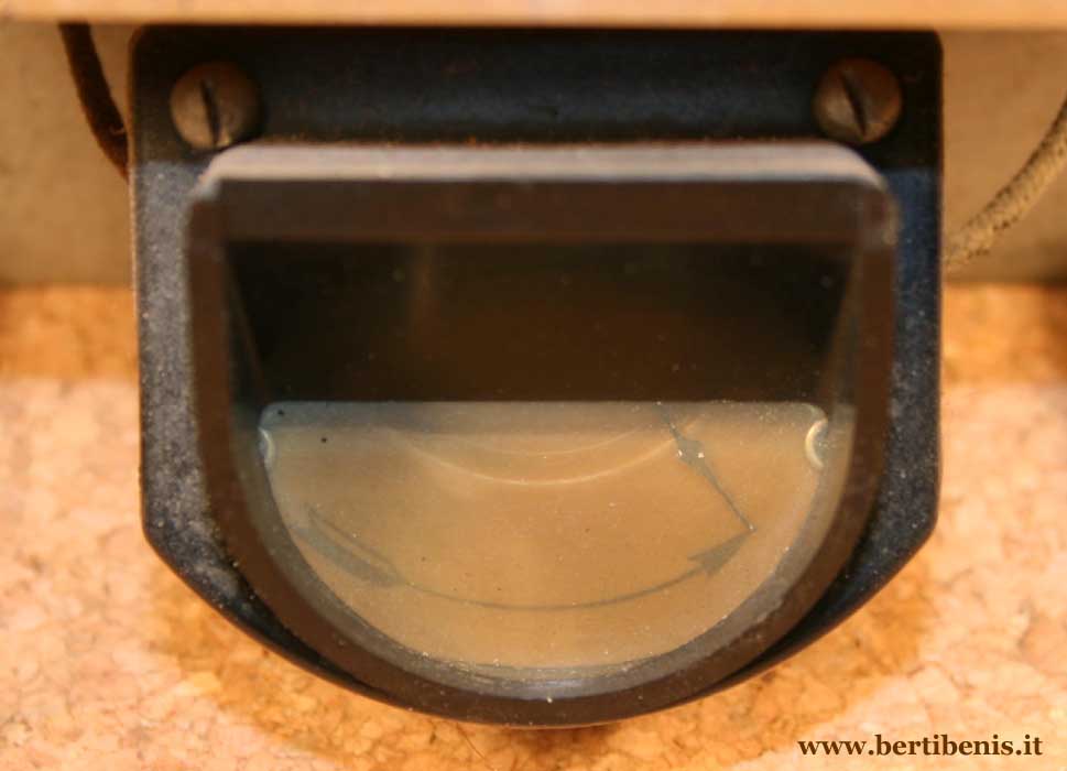
waves band. Under
the dial you can see a pointer tuning meter which works in series to
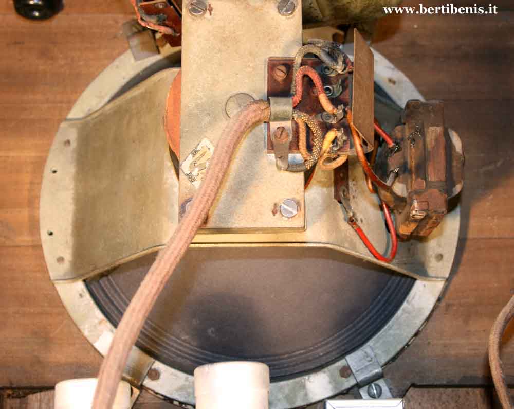
the anodic circuit of the IF amplifier tube. Exists a doubt about the muting switch operating of this radio, so I put
in the bottom of the page three electrical diagrams which I found in
three different books of the age: In the first diagram there is a mistake and the switch is missing. In the
Damayante diagram the switch is located in series to the sound
speaker coil. In the third diagram the switch is located in series
to the LF signal, between the 75 and 41 tubes. The published radio, and other two radios that I’ve seen, corresponds
at the second diagram, the one of Damayante. |
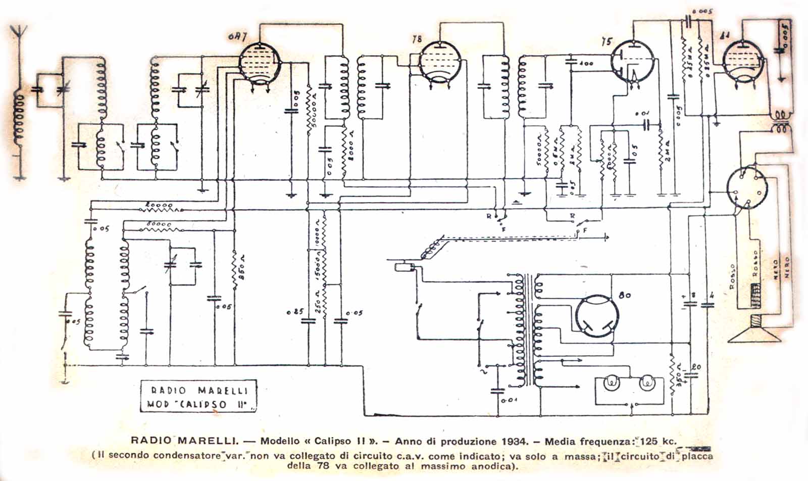
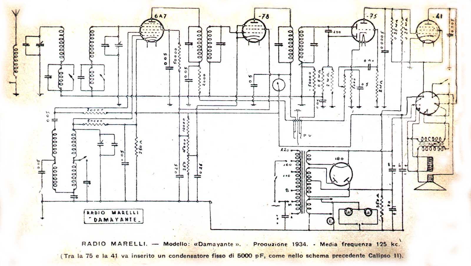
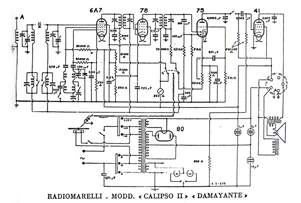
First diagram Damayante diagram Third diagram